Interface definitions for the SpinAPI library. More...
Data Structures | |
| struct | PB_OVERFLOW_STRUCT |
| Overflow counter structure. More... | |
Functions | |
| SPINCORE_API int | pb_count_boards (void) |
| SPINCORE_API int | pb_select_board (int board_num) |
| SPINCORE_API int | pb_init (void) |
| SPINCORE_API void | pb_core_clock (double clock_freq) |
| SPINCORE_API int | pb_close (void) |
| SPINCORE_API int | pb_start_programming (int device) |
| SPINCORE_API int | pb_set_freq (double freq) |
| SPINCORE_API int | pb_set_phase (double phase) |
| SPINCORE_API int | pb_inst_tworf (int freq, int tx_phase, int tx_output_enable, int rx_phase, int rx_output_enable, int flags, int inst, int inst_data, double length) |
| SPINCORE_API int | pb_zero_ram () |
| SPINCORE_API int | pb_inst_onerf (int freq, int phase, int rf_output_enable, int flags, int inst, int inst_data, double length) |
| SPINCORE_API int | pb_4C_inst (int flag, double length) |
| SPINCORE_API int | pb_4C_stop (void) |
| SPINCORE_API int | pb_inst_pbonly (unsigned int flags, int inst, int inst_data, double length) |
| SPINCORE_API int | pb_inst_pbonly64 (__int64 flags, int inst, int inst_data, double length) |
| SPINCORE_API int | pb_inst_direct (int *pflags, int inst, int inst_data_direct, int length) |
| SPINCORE_API int | pb_stop_programming (void) |
| SPINCORE_API int | pb_start (void) |
| SPINCORE_API int | pb_stop (void) |
| SPINCORE_API int | pb_reset (void) |
| SPINCORE_API int | pb_outp (unsigned int address, char data) |
| SPINCORE_API char | pb_inp (unsigned int address) |
| SPINCORE_API int | pb_outw (unsigned int address, unsigned int data) |
| SPINCORE_API unsigned int | pb_inw (unsigned int address) |
| SPINCORE_API void | pb_set_ISA_address (int address) |
| SPINCORE_API double | pb_get_rounded_value (void) |
| SPINCORE_API int | pb_read_status (void) |
| SPINCORE_API char * | pb_status_message (void) |
| SPINCORE_API char * | pb_get_version (void) |
| SPINCORE_API char * | pb_get_error (void) |
| SPINCORE_API int | pb_get_firmware_id (void) |
| SPINCORE_API void | pb_sleep_ms (int milliseconds) |
| SPINCORE_API void | pb_set_debug (int debug) |
| SPINCORE_API void | pb_bypass_FF_fix (int option) |
| SPINCORE_API int | pb_inst_hs8 (char *Flags, double length) |
| SPINCORE_API int | pb_inst_hs24 (char *Flags, double length) |
| SPINCORE_API int | set_pts (double maxFreq, int is160, int is3200, int allowPhase, int noPTS, double frequency, int phase) |
| SPINCORE_API int | set_pts_ex (int pts_index, double maxFreq, int is160, int is3200, int allowPhase, int noPTS, double frequency, int phase) |
| SPINCORE_API char * | spinpts_get_error () |
| SPINCORE_API char * | spinpts_get_version () |
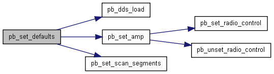
| SPINCORE_API int | pb_set_defaults (void) |
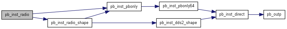
| SPINCORE_API int | pb_inst_radio (int freq, int cos_phase, int sin_phase, int tx_phase, int tx_enable, int phase_reset, int trigger_scan, int flags, int inst, int inst_data, double length) |
| SPINCORE_API int | pb_inst_radio_shape (int freq, int cos_phase, int sin_phase, int tx_phase, int tx_enable, int phase_reset, int trigger_scan, int use_shape, int amp, int flags, int inst, int inst_data, double length) |
| SPINCORE_API int | pb_inst_radio_shape_cyclops (int freq, int cos_phase, int sin_phase, int tx_phase, int tx_enable, int phase_reset, int trigger_scan, int use_shape, int amp, int real_add_sub, int imag_add_sub, int channel_swap, int flags, int inst, int inst_data, double length) |
| SPINCORE_API int | pb_set_num_points (int num_points) |
| SPINCORE_API int | pb_set_scan_segments (int num_segments) |
| SPINCORE_API int | pb_scan_count (int reset) |
| SPINCORE_API int | pb_overflow (int reset, PB_OVERFLOW_STRUCT *of) |
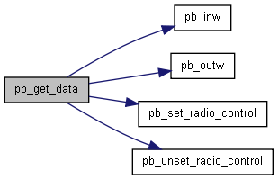
| SPINCORE_API int | pb_get_data (int num_points, int *real_data, int *imag_data) |
| SPINCORE_API int | pb_get_data_direct (int num_points, short *data) |
| SPINCORE_API int | pb_write_ascii (char *fname, int num_points, float SW, int *real_data, int *imag_data) |
| SPINCORE_API int | pb_write_ascii_verbose (char *fname, int num_points, float SW, float SF, int *real_data, int *imag_data) |
| SPINCORE_API int | pb_write_jcamp (char *fname, int num_points, float SW, float SF, int *real_data, int *imag_data) |
| SPINCORE_API int | pb_write_felix (char *fnameout, char *title_string, int num_points, float SW, float SF, int *real_data, int *imag_data) |
| SPINCORE_API int | pb_setup_filters (double spectral_width, int scan_repetitions, int cmd) |
| SPINCORE_API int | pb_setup_cic (int dec_amount, int shift_amount, int m, int stages) |
| SPINCORE_API int | pb_load_coef_file (int *coef, char *fname, int num_coefs) |
| SPINCORE_API int | pb_setup_fir (int num_taps, int *coef, int shift_amount, int dec_amount) |
| SPINCORE_API int | pb_set_radio_control (unsigned int control) |
| SPINCORE_API int | pb_unset_radio_control (unsigned int control) |
| SPINCORE_API int | pb_select_core (unsigned int core_sel) |
| SPINCORE_API int | pb_adc_zero (int set) |
| SPINCORE_API int | pb_set_pulse_regs (unsigned int channel, double period, double clock_high, double offset) |
| SPINCORE_API int | pb_inst_dds2_shape (int freq0, int phase0, int amp0, int use_shape0, int dds_en0, int phase_reset0, int freq1, int phase1, int amp1, int use_shape1, int dds_en1, int phase_reset1, int flags, int inst, int inst_data, double length) |
| SPINCORE_API int | pb_set_shape_defaults (void) |
| SPINCORE_API int | pb_dds_load (float *data, int device) |
| SPINCORE_API int | pb_set_amp (float amp, int addr) |
| SPINCORE_API int | pb_fft (int n, int *real_in, int *imag_in, double *real_out, double *imag_out, double *mag_fft) |
| SPINCORE_API double | pb_fft_find_resonance (int num_points, double SF, double SW, int *real, int *imag) |
| SPINCORE_API int | pb_shift_data_left (int num_points, int points_shift, int val_shift, int *real_in, int *imag_in, int *real_out, int *imag_out) |
| SPINCORE_API int | pb_shift_data_right (int num_points, int points_shift, int val_shift, int *real_in, int *imag_in, int *real_out, int *imag_out) |
Detailed Description
Interface definitions for the SpinAPI library.
To get the latest version of this code, or to contact us for support, please visit http://www.spincore.com
Function Documentation
| SPINCORE_API int pb_count_boards | ( | void | ) |
Return the number of SpinCore boards present in your system.
- Returns:
- The number of boards present is returned. -1 is returned on error, and spinerr is set to a description of the error.
| SPINCORE_API int pb_select_board | ( | int | board_num | ) |
If multiple boards from SpinCore Technologies are present in your system, this function allows you to select which board to talk to. Once this function is called, all subsequent commands (such as pb_init(), pb_set_clock(), etc.) will be sent to the selected board. You may change which board is selected at any time.
If you have only one board, it is not necessary to call this function.
- Parameters:
-
board_num Specifies which board to select. Counting starts at 0.
- Returns:
- A negative number is returned on failure, and spinerr is set to a description of the error. 0 is returned on success.

| SPINCORE_API int pb_init | ( | void | ) |
Initializes the board. This must be called before any other functions are used which communicate with the board. If you have multiple boards installed in your system, pb_select_board() may be called first to select which board to initialize.
- Returns:
- A negative number is returned on failure, and spinerr is set to a description of the error. 0 is returned on success.

| SPINCORE_API void pb_core_clock | ( | double | clock_freq | ) |
Tell the library what clock frequency the board uses. This should be called at the beginning of each program, right after you initialize the board with pb_init(). Note that this does not actually set the clock frequency, it simply tells the driver what frequency the board is using, since this cannot (currently) be autodetected.
Also note that this frequency refers to the speed at which the PulseBlaster core itself runs. On many boards, this is different than the value printed on the oscillator. On RadioProcessor devices, the A/D converter and the PulseBlaster core operate at the same clock frequency.
- Parameters:
-
clock_freq Frequency of the clock in MHz.
| SPINCORE_API int pb_close | ( | void | ) |
End communication with the board. This is generally called as the last line in a program. Once this is called, no further communication can take place with the board unless the board is reinitialized with pb_init(). However, any pulse program that is loaded and running at the time of calling this function will continue to run indefinitely.
- Returns:
- A negative number is returned on failure, and spinerr is set to a description of the error. 0 is returned on success.
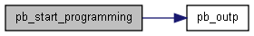
| SPINCORE_API int pb_start_programming | ( | int | device | ) |
This function tells the board to start programming one of the onboard devices. For all the devices, the method of programming follows the following form:
a call to pb_start_programming(), a call to one or more functions which transfer the actual data, and a call to pb_stop_programming(). Only one device can be programmed at a time.
- Parameters:
-
device Specifies which device to start programming. Valid devices are: - PULSE_PROGRAM - The pulse program will be programmed using one of the pb_inst* instructions.
- FREQ_REGS - The frequency registers will be programmed using the pb_set_freq() function. (DDS and RadioProcessor boards only)
- TX_PHASE_REGS - The phase registers for the TX channel will be programmed using pb_set_phase() (DDS and RadioProcessor boards only)
- RX_PHASE_REGS - The phase registers for the RX channel will be programmed using pb_set_phase() (DDS enabled boards only)
- COS_PHASE_REGS - The phase registers for the cos (real) channel (RadioProcessor boards only)
- SIN_PHASE_REGS - The phase registers for the sine (imaginary) channel (RadioProcessor boards only)
- Returns:
- A negative number is returned on failure, and spinerr is set to a description of the error. 0 is returned on success.
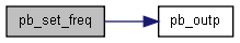
| SPINCORE_API int pb_set_freq | ( | double | freq | ) |
Write the given frequency to a frequency register on a DDS enabled board. To do this, first call pb_start_programming(), and pass it FREQ_REGS. The first call pb_set_freq() will then program frequency register 0, the second call will program frequency register 1, etc. When you have programmed all the registers you intend to, call pb_stop_programming()
- Parameters:
-
freq The frequency in MHz to be programmed to the register.
- Returns:
- A negative number is returned on failure, and spinerr is set to a description of the error. 0 is returned on success.
| SPINCORE_API int pb_set_phase | ( | double | phase | ) |
Write the given phase to a phase register on DDS enabled boards. To do this, first call pb_start_programming(), and specify the appropriate bank of phase registers (such as TX_PHASE, RX_PHASE, etc) as the argument. The first call pb_set_phase() will then program phase register 0, the second call will program phase register 1, etc. When you have programmed all the registers you intend to, call pb_stop_programming()
The given phase value may be rounded to fit the precision of the board.
- Parameters:
-
phase The phase in degrees to be programmed to the register.
- Returns:
- A negative number is returned on failure, and spinerr is set to a description of the error. 0 is returned on success.
| SPINCORE_API int pb_inst_tworf | ( | int | freq, | |
| int | tx_phase, | |||
| int | tx_output_enable, | |||
| int | rx_phase, | |||
| int | rx_output_enable, | |||
| int | flags, | |||
| int | inst, | |||
| int | inst_data, | |||
| double | length | |||
| ) |
Program an instruction of a pulse program to the board. This function programs instructions for boards with 2 DDS outputs. (such as PulseBlasterDDS-III) There are other forms of this instruction (see below) design to program boards with differing instruction formats.
Instructions can also be programmed by calling pb_inst(), but you must use an appropriate define before including spinapi.h. See the example programs for how to do this.
- Parameters:
-
freq The frequency register to use for this instruction tx_phase The TX phase register to use for this instruction tx_output_enable Set to ANALOG_ON to enable output, or ANALOG_OFF to output nothing rx_phase The RX phase register to use for this instruction rx_output_enable Set to ANALOG_ON to enable output, or ANALOG_OFF to output nothing flags Set every bit to one for each flag you want to set high inst Specify the instruction you want. Valid instructions are: Opcode # Instruction Meaning of inst_data field 0 CONTINUE Not Used 1 STOP Not Used 2 LOOP Number of desired loops 3 END_LOOP Address of instruction originating loop 4 JSR Address of first instruction in subroutine 5 RTS Not Used 6 BRANCH Address of instruction to branch to 7 LONG_DELAY Number of desired repetitions 8 WAIT Not Used See your board manual for a detailed description of each instruction.
inst_data Instruction specific data. Internally this is a 20 bit unsigned number, so the largest value that can be passed is 2^20-1 (the largest value possible for a 20 bit number). See above table to find out what this means for each instruction. length Length of this instruction in nanoseconds.
- Returns:
- The address of the created instruction is returned. This can be used as the branch address for any branch instructions. A negative number is returned on failure, and spinerr is set to a description of the error.

| SPINCORE_API int pb_zero_ram | ( | ) |
Deprecated function. Included only to avoid breaking old code.
- Returns:
- Always returns 0
| SPINCORE_API int pb_inst_onerf | ( | int | freq, | |
| int | phase, | |||
| int | rf_output_enable, | |||
| int | flags, | |||
| int | inst, | |||
| int | inst_data, | |||
| double | length | |||
| ) |
This is the instruction programming function for boards with only one DDS output channel. Syntax is identical to that of pb_inst_tworf(), but the second RF channel is not used.

| SPINCORE_API int pb_4C_inst | ( | int | flag, | |
| double | length | |||
| ) |
This function is used to write a pulse program to any PulseBlaster QuadCore design
- Parameters:
-
flag Output flag pattern for the current instruction. length Length of the current instruction in nanoseconds.
- Returns:
- Returns 0 on success.

| SPINCORE_API int pb_4C_stop | ( | void | ) |
This function is used to stop operation of a pulse program on the specified core when using any PulseBlaster QuadCore design.
- Returns:
- Returns 0 on success.

| SPINCORE_API int pb_inst_pbonly | ( | unsigned int | flags, | |
| int | inst, | |||
| int | inst_data, | |||
| double | length | |||
| ) |
This is the instruction programming function for boards without a DDS. (for example PulseBlaster and PulseBlasterESR boards). Syntax is identical to that of pb_inst_tworf(), except that the parameters pertaining to the analog outputs are not used.

| SPINCORE_API int pb_inst_pbonly64 | ( | __int64 | flags, | |
| int | inst, | |||
| int | inst_data, | |||
| double | length | |||
| ) |
This is the instruction programming function for boards without a DDS. (for example PulseBlaster and PulseBlasterESR boards). Syntax is identical to that of pb_inst_tworf(), except that the parameters pertaining to the analog outputs are not used.

| SPINCORE_API int pb_inst_direct | ( | int * | pflags, | |
| int | inst, | |||
| int | inst_data_direct, | |||
| int | length | |||
| ) |
This function allows you to directly specify the fields for an instruction, which will then be passed directly to the board without any modification by software. See your product manual for a discussion of the meaning of each field.
This function is provided mainly to help us debug the boards. It is highly recommended that users make use the higher level instruction functions such as pb_inst(), pb_inst_pbonly(), pb_inst_tworf(), pb_inst_radio(). These allow the creation of instructions in a more user-friendly manner and also perform additional error checking to help you avoid accidentally using paramaters that are out of range for your board.
- Parameters:
-
flags Flag field inst Instruction (4 bits) inst_data_direct Instruction data (20 bits) Unlike the other pb_inst* instructions, this field is passed directly to the board and not adjusted based on the instruction used. (eg, using a value of 2 for a loop instruction will cause 3 loops to happen. The other pb_inst* functions would modify this value so the number of loops entered is the number produced) length Delay field (32 bits) Note that this is the value is NOT the number of clock cycles an instruction will execute for. There is typically an additional fixed internal delay which is added to produce the actual delay.
| SPINCORE_API int pb_stop_programming | ( | void | ) |
Finishes the programming for a specific onboard devices which was started by pb_start_programming().
- Returns:
- A negative number is returned on failure, and spinerr is set to a description of the error. 0 is returned on success.

| SPINCORE_API int pb_start | ( | void | ) |
Send a software trigger to the board. This will start execution of a pulse program. It will also trigger a program which is currently paused due to a WAIT instruction. Triggering can also be accomplished through hardware, please see your board's manual for details on how to accomplish this.
- Returns:
- A negative number is returned on failure, and spinerr is set to a description of the error. 0 is returned on success.
| SPINCORE_API int pb_stop | ( | void | ) |
Stops output of board. Analog output will return to ground, and TTL outputs will either remain in the same state they were in when the reset command was received or return to ground. This also resets the PulseBlaster so that the PulseBlaster Core can be run again using pb_start() or a hardware trigger.
- Returns:
- A negative number is returned on failure, and spinerr is set to a description of the error. 0 is returned on success.
| SPINCORE_API int pb_reset | ( | void | ) |
Stops the output of board and resets the PulseBlaster Core. Analog output will return to ground, and TTL outputs will either remain in the same state they were in when the reset command was received or return to ground. This also resets the PulseBlaster Core so that the board can be run again using pb_start() or a hardware trigger. Note: Either pb_reset() or pb_stop() must be called before pb_start() if the pulse program is to be run from the beginning (as opposed to continuing from a WAIT state).
- Returns:
- A negative number is returned on failure, and spinerr is set to a description of the error. 0 is returned on success.

| SPINCORE_API int pb_outp | ( | unsigned int | address, | |
| char | data | |||
| ) |
Write 1 byte to the given PCI I/O address. This is a low level hardware access function.
- Parameters:
-
address The I/O Register to write to data The byte to write
Low level IO functions. Typically the end user will use the above functions to access the hardware, and these functions are mainly included in the API for backwards compatibility.
| SPINCORE_API char pb_inp | ( | unsigned int | address | ) |
Read 1 byte from the given PCI I/O address. This is a low level hardware access function.
- Parameters:
-
address The I/O Register to read
- Returns:
- The byte requested is returned.
| SPINCORE_API int pb_outw | ( | unsigned int | address, | |
| unsigned int | data | |||
| ) |
Write a 32 bit (4 byte) word to the given PCI I/O address. This is a low level hardware access function.
- Parameters:
-
address The I/O Register to write to. This should be a multiple of 4. data The word to write
| SPINCORE_API unsigned int pb_inw | ( | unsigned int | address | ) |
Read a 32 bit (4 byte) word from the given PCI I/O address. This is a low level hardware access function.
- Parameters:
-
address The I/O Register to read. This should be a multiple of 4.
- Returns:
- The word requested is returned.
| SPINCORE_API void pb_set_ISA_address | ( | int | address | ) |
For ISA Boards only. Specify the base address of the board. If you have a PCI board, any call to this function is ignored.
- Parameters:
-
address base address of the ISA board
| SPINCORE_API double pb_get_rounded_value | ( | void | ) |
Many parameters to funciton in the API are given as full precision double values, such as the length of an instruction, or the phase to be programmed to a phase register. Since the hardware does not have the full precision of a double value, the paremeters are rounded to match the internal precision. This function allows you to see what to what value the parameters were rounded.
- Returns:
- The last value rounded by the API.
| SPINCORE_API int pb_read_status | ( | void | ) |
Read status from the board. Not all boards support this, see your manual. Each bit of the returned integer indicates whether the board is in that state. Bit 0 is the least significant bit.
- Bit 0 - Stopped
- Bit 1 - Reset
- Bit 2 - Running
- Bit 3 - Waiting
- Bit 4 - Scanning (RadioProcessor boards only)
Note on Bit 1: Bit 1 will be high, '1', as soon as the board is initialized. It will remain high until a hardware or software reset occurs. At that point, it will stay low, '0', until the board is triggered again.
Bits 5-31 are reserved for future use. It should not be assumed that these will be set to 0.
- Returns:
- Word that indicates the state of the current board as described above.
| SPINCORE_API char* pb_status_message | ( | void | ) |
Read status message from the board. Not all boards support this, see your manual. The returned string will either have the board's status or an error message
- Returns:
- String containing the status message of the board.

| SPINCORE_API char* pb_get_version | ( | void | ) |
Get the version of this library. The version is a string in the form YYYYMMDD.
- Returns:
- A string indicating the version of this library is returned.
| SPINCORE_API char* pb_get_error | ( | void | ) |
Return the most recent error string. Anytime a function (such as pb_init(), pb_start_programming(), etc.) encounters an error, this function will return a description of what went wrong.
- Returns:
- A string describing the last error is returned. A string containing "No Error" is returned if the last function call was successfull.
| SPINCORE_API int pb_get_firmware_id | ( | void | ) |
Get the firmware version on the board. This is not supported on all boards.
- Returns:
- Returns the firmware id as described above. A 0 is returned if the firmware id feature is not available on this version of the board.
| SPINCORE_API void pb_sleep_ms | ( | int | milliseconds | ) |
This function allows you to pause execution of your software for a given number of milliseconds, and behaves like the sleep() function found on many operating systems. This is provided because the sleep() function is not standard across all operating systems/programming environments.
This function does *NOT* interact with the hardware or pulse program at all. It simply provides a portable way to access a sleep function.
- Parameters:
-
milliseconds Number of milliseconds to sleep (pause program) for.
| SPINCORE_API void pb_set_debug | ( | int | debug | ) |
Enable debug log. When enabled, spinapi will generate a file called log.txt, which contains some debugging information. This file is probably not very useful for the end-user, but if you are encountering difficulty, it will help us to turn debugging on and email us the log along with your support question.
- Parameters:
-
debug Set to 1 to turn on debugging outputs, or 0 to turn off.
| SPINCORE_API void pb_bypass_FF_fix | ( | int | option | ) |
This function allows you to modify the behavior of the PB CORE counter fix. Do not use this funtion unless advised to do so.
- Parameters:
-
option Set to 0 to turn on the fix, 1 to turn it off.
| SPINCORE_API int pb_inst_hs8 | ( | char * | Flags, | |
| double | length | |||
| ) |
This function is for PBESR-PRO-II designs. It allows for 8 bit operation.
This function expects standard ASCII input characters ('1' is ASCII 49, '0' is ASCII 48). If you have an international version of Windows that uses a character set other than ASCII, you may need to modify this function.
- Parameters:
-
Flags String of 8 1s and 0s corresponding to the 8 flag bits(from left to right: Channel 7, Channel 6, Channel 5, etc.) length Floating point number, representing the desired pulse length, in nanoseconds
- Returns:
- A negative number is returned on failure and spinerr is set to a description of the error. The number of clock cycles used is returned on success.
| SPINCORE_API int pb_inst_hs24 | ( | char * | Flags, | |
| double | length | |||
| ) |
This function is for PBESR-PRO-II designs. It allows for 24 bit operation.
This function expects standard ASCII input characters ('1' is ASCII 49, '0' is ASCII 48). If you have an international version of Windows that uses a character set other than ASCII, you may need to modify this function.
- Parameters:
-
Flags String of 24 1s and 0s corresponding to the 24 flag bits(from left to right: Channel 23, Channel 22, Channel 21, ... , Channel 0) length Floating point number, representing the desired pulse length, in nanoseconds
- Returns:
- A negative number is returned on failure and spinerr is set to a description of the error. The number of clock cycles used is returned on success.
| SPINCORE_API int set_pts | ( | double | maxFreq, | |
| int | is160, | |||
| int | is3200, | |||
| int | allowPhase, | |||
| int | noPTS, | |||
| double | frequency, | |||
| int | phase | |||
| ) |
Set the frequency and phase to the first available PTS Device. The PTSDevice parameter is optional. Specifying a PTS Device structure will include frequency and phase bounds checking when setting the device.
- Parameters:
-
frequency Double values (greater than 0.) phase Must be equal to 0, 90, 180, 270 device (OPTIONAL) Pointer to PTSDevice structure. This argument can be NULL.
- Returns:
- Returns 0 if no error occured. If an error occurs, returns an error code defined in spinpts.h
| SPINCORE_API int set_pts_ex | ( | int | pts_index, | |
| double | maxFreq, | |||
| int | is160, | |||
| int | is3200, | |||
| int | allowPhase, | |||
| int | noPTS, | |||
| double | frequency, | |||
| int | phase | |||
| ) |
Set the frequency and phase to a specific PTS Device. The PTSDevice parameter is optional. Specifying a PTS Device structure will include frequency and phase bounds checking when setting the device.
- Parameters:
-
pts_index Which PTS device to set. 1 corresponds to the first available device, 2 to the second and so forth. frequency Double values (greater than 0.) phase Must be equal to 0, 90, 180, 270 device (OPTIONAL) Pointer to PTSDevice structure. This argument can be NULL.
- Returns:
- Returns 0 if no error occured. If an error occurs, returns an error code defined in spinpts.h
| SPINCORE_API char* spinpts_get_error | ( | ) |
Decodes error codes defined in spinpts.h
- Returns:
- Returns a pointer to a C string containing the error description.
| SPINCORE_API char* spinpts_get_version | ( | ) |
Gets the current version of the SpinPTS API being used.
- Returns:
- Returns a pointer to a C string containing the version string.
| SPINCORE_API int pb_set_defaults | ( | void | ) |
This function sets the RadioProcessor to its default state. It has no effect on any other SpinCore product. This function should generally be called after pb_init() to make sure the RadioProcessor is in a usable state. It is REQUIRED that this be called at least once after the board is powered on. However, there are a few circumstances when you would not call this function. In the case where you had one program that configured the RadioProcessor, and another seperate program which simply called pb_start() to start the experiment, you would NOT call pb_set_defaults() in the second program because this would overwrite the configuration set by the first program.
- Returns:
- A negative number is returned on failure, and spinerr is set to a description of the error. 0 is returned on success.
| SPINCORE_API int pb_inst_radio | ( | int | freq, | |
| int | cos_phase, | |||
| int | sin_phase, | |||
| int | tx_phase, | |||
| int | tx_enable, | |||
| int | phase_reset, | |||
| int | trigger_scan, | |||
| int | flags, | |||
| int | inst, | |||
| int | inst_data, | |||
| double | length | |||
| ) |
Program an instruction of the pulse program.
- Parameters:
-
freq Selects which frequency register to use cos_phase Selects which phase register to use for the cos (real) channel sin_phase Selects which phase register to use for the sin (imaginary) channel tx_phase Selects which phase register to use for the TX channel tx_enable When this is 1, the TX channel will be output on the Analog Out connector. When this is 0, Analog Out channel will be turned off. phase_reset When this is 1, the phase of all DDS channels will be reset to their time=0 phase. They will stay in this state until the value of this bit returns to 0. trigger_scan When this is 1, a scan will be triggered. To start a second scan, this bit must be set to 0 and then back to 1. flags Controls the state of the user available digital out pins. Since there are 6 user outputs, only the lower 6 bits of this parameter are used. Bits 1 and 0 control BNC1 and BNC0 respectively. inst Which instruction to use. See manual for details. inst_data Some instructions require additional data. This allows that data to be specified. See manual for details. length Time until the next instruction is executed in nanoseconds
| SPINCORE_API int pb_inst_radio_shape | ( | int | freq, | |
| int | cos_phase, | |||
| int | sin_phase, | |||
| int | tx_phase, | |||
| int | tx_enable, | |||
| int | phase_reset, | |||
| int | trigger_scan, | |||
| int | use_shape, | |||
| int | amp, | |||
| int | flags, | |||
| int | inst, | |||
| int | inst_data, | |||
| double | length | |||
| ) |
Write an instruction that makes use of the pulse shape feature of some RadioProcessor boards. This adds two new paramters, use_shape and amp, which control the shape feature. All other parameters are identical to the pb_inst_radio() function. If you do not wish to use the shape feature, the pb_inst_radio() function can be used instead.
- Parameters:
-
use_shape Select whether or not to use shaped pulses. If this is 0, a regular non-shaped pulse (hard pulse) is output. If it is nonzero, the shaped pulse is used. The pulse shape waveform can be set using the pb_dds_load() function. amp Select which amplitude register to use. The values of the amplitude registers can be set with pb_set_amp()

| SPINCORE_API int pb_inst_radio_shape_cyclops | ( | int | freq, | |
| int | cos_phase, | |||
| int | sin_phase, | |||
| int | tx_phase, | |||
| int | tx_enable, | |||
| int | phase_reset, | |||
| int | trigger_scan, | |||
| int | use_shape, | |||
| int | amp, | |||
| int | real_add_sub, | |||
| int | imag_add_sub, | |||
| int | channel_swap, | |||
| int | flags, | |||
| int | inst, | |||
| int | inst_data, | |||
| double | length | |||
| ) |
Write an instruction that makes use of the pulse shape feature of some RadioProcessor boards. This adds two new paramters, use_shape and amp, which control the shape feature. All other parameters are identical to the pb_inst_radio() function. If you do not wish to use the shape feature, the pb_inst_radio() function can be used instead.
- Parameters:
-
use_shape Select whether or not to use shaped pulses. If this is 0, a regular non-shaped pulse (hard pulse) is output. If it is nonzero, the shaped pulse is used. The pulse shape waveform can be set using the pb_dds_load() function. amp Select which amplitude register to use. The values of the amplitude registers can be set with pb_set_amp()

| SPINCORE_API int pb_set_num_points | ( | int | num_points | ) |
Set the number of complex points to capture. This is typically set to the size of the onboard RAM, but a smaller value can be used if all points are not needed.
- Parameters:
-
num_points The number of complex points to capture
- Returns:
- A negative number is returned on failure, and spinerr is set to a description of the error. 0 is returned on success.
| SPINCORE_API int pb_set_scan_segments | ( | int | num_segments | ) |
Set the number of data "segments" to be acquired. The default value is 1, meaning when data is acquired, it will be stored to the RAM starting at address zero, and continue until the desired number of points are acquired. Any subsequent data acquisition scans will behave in the same way and thus overwrite (or average with) the previous data. If num_segments is set to a value higher than 1, the given number of segments will be acquired before resetting the ram address to 0. For example if num_points is set to 1000, and num_segments is set to 3, the first time the acquisition is triggered (using scan_trigger), data will be written to RAM locations 0-999. The second time it is triggered, data will be written to locations 1000-1999 (instead of writing again to locations 0-999 as would be the case for num_segments = 1). On the third trigger data will go to locations 2000-2999. Finally a fourth trigger would again write to locations 0-999, and the cycle will continue as desired.
When this function is called, the internal segment counter is reset to segment 0.
- Parameters:
-
num_segments Number of segments to acquire. Must be between 1 and 65535.
- Returns:
- A negative number is returned on failure, and spinerr is set to a description of the error. 0 is returned on success.
| SPINCORE_API int pb_scan_count | ( | int | reset | ) |
Get the current value of the scan count register, or reset the register to 0. This function can be used to monitor the progress of an experiment if multiple scans are being performed.
- Parameters:
-
reset If this parameter is set to 1, this function will reset the scan counter to 0. If reset is 0, this function will return the current value of the scan counter.
- Returns:
- The number of scans performed since the last reset is returned when reset=0. -1 is returned on error
| SPINCORE_API int pb_overflow | ( | int | reset, | |
| PB_OVERFLOW_STRUCT * | of | |||
| ) |
Retrieve the contents of the overflow registers. This can be used to find out if the ADC is being driven with to large of a signal. In addition, the RadioProcessor must round data values at certain points during the processing of the signal. By default, this rounding is done in such a way that overflows cannot occur. However, if you change the rounding procedure, this function will allow you to determine if overflows have occurred. Each overflow register counts the number of overflows up to 65535. If more overflows than this occur, the register will remain at 65535. The overflow registers can reset by setting the reset argument of this function to 1.
See your manual for a detailed explanation of how the on-board rounding works.
- Parameters:
-
reset Set this to one to reset the overflow counters of Pointer to a PB_OVERFLOW_STRUCT which will hold the values of the overflow counter. This can be a NULL pointer if you are using this function to reset the counters
- Returns:
- A negative number is returned on failure, and spinerr is set to a description of the error. 0 is returned on success.
| SPINCORE_API int pb_get_data | ( | int | num_points, | |
| int * | real_data, | |||
| int * | imag_data | |||
| ) |
Retrieve the captured data from the board's memory. Data is returned as a signed 32 bit integer. Data can be accessed at any time, even while the data from a scan is being captured. However, this is not recommened since there is no way to tell what data is part of the current scan and what is part of the previous scan.
pb_read_status() can be used to determine whether or not a scan is currently in progress.
It takes approximately 160ms to transfer all 16k complex points.
- Parameters:
-
num_points Number of complex points to read from RAM real_data Real data from RAM is stored into this array imag_data Imag data from RAM is stored into this array
- Returns:
- A negative number is returned on failure, and spinerr is set to a description of the error. 0 is returned on success.
| SPINCORE_API int pb_get_data_direct | ( | int | num_points, | |
| short * | data | |||
| ) |
Retrieve captured data from the board's memory. Use this function instead of pb_get_data() if you have used the direct capture (data points are sent from the A/D directly to RAM with no modification) capabilities of the board. Direct capture points are the raw 14 bit, signed data from the A/D and are returned as an array of 16 bit short integers.
You can enable direct capture by calling the function pb_set_radio_control(RAM_DIRECT)
In direct capture mode, a USB board will acquire 4x the number of points you set with pb_set_num_points()
- Parameters:
-
num_points Number of direct capture points to retrieve data Storage space for the data points. This must contain enough room
- Returns:
- A negative number is returned on failure, and spinerr is set to a description of the error. 0 is returned on success.
| SPINCORE_API int pb_write_ascii | ( | char * | fname, | |
| int | num_points, | |||
| float | SW, | |||
| int * | real_data, | |||
| int * | imag_data | |||
| ) |
Deprecated legacy function. Please use pb_write_ascii_verbose instead.

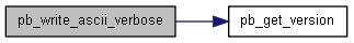
| SPINCORE_API int pb_write_ascii_verbose | ( | char * | fname, | |
| int | num_points, | |||
| float | SW, | |||
| float | SF, | |||
| int * | real_data, | |||
| int * | imag_data | |||
| ) |
Write the data captured from RAM to an ascii file. The file format produced is: The first three lines are comments containing information about the RadioProcessor and SpinAPI. The fourth line contains the number of complex points, the fifth line contains the spectrometer frequency (in MHz), the sixth line contains the spectral width of the data (in Hz), and the remaining lines contain the complex points themselves. Real and Imaginary compoents of the complex points are given on alternate lines. Thus, the real and imaginary components of the first point are given on lines 7 and 8 respectively. The second point is given on lines9 and 10, etc.
- Parameters:
-
fname Filename to write the data to num_points Number of complex data points to write SW Spectral width in Hz. This should be set to the spectral width of the stored baseband data. SF Spectrometer frequency in MHz real_data Array holding the real portion of the complex data points imag_data Array holding the imaginary portion of the complex data points
- Returns:
- A negative number is returned on failure, and spinerr is set to a description of the error. 0 is returned on success.
| SPINCORE_API int pb_write_jcamp | ( | char * | fname, | |
| int | num_points, | |||
| float | SW, | |||
| float | SF, | |||
| int * | real_data, | |||
| int * | imag_data | |||
| ) |
Write the RAM contents to a JCAMP-DX file.
- Parameters:
-
fname The filename for the file you want to create num_points Number of points to write to the file SW Spectral width of the baseband data in Hz SF Spectrometer frequency in MHz real_data Integer array containing the real portion of the data points imag_data Integer array containing the imaginary portion of the data points
- Returns:
- A negative number is returned on failure, and spinerr is set to a description of the error. 0 is returned on success. Write the RAM contents to a JCAMP-DX file.
- Parameters:
-
fname The filename for the file you want to create num_points Number of points to write to the file SW Spectral width of the baseband data in Hz SF Spectrometer frequency in MHz real_data Integer array containing the real portion of the data points imag_data Integer array containing the imaginary portion of the data points
- Returns:
- A negative number is returned on failure, and spinerr is set to a description of the error. 0 is returned on success.
| SPINCORE_API int pb_write_felix | ( | char * | fnameout, | |
| char * | title_string, | |||
| int | num_points, | |||
| float | SW, | |||
| float | SF, | |||
| int * | real_data, | |||
| int * | imag_data | |||
| ) |
Write the RAM contents to a Felix file.
- Parameters:
-
fnameout The filename for the Felix file you want to create title_string Large string with all parameter information to include in Felix Title Block num_points Number of points to write to the file SW Spectral width of the baseband data in Hz SF Spectrometer frequency in MHz real_data Integer array containing the real portion of the data points imag_data Integer array containing the imaginary portion of the data points
- Returns:
- A negative number is returned on failure, and spinerr is set to a description of the error. 0 is returned on success.

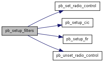
| SPINCORE_API int pb_setup_filters | ( | double | spectral_width, | |
| int | scan_repetitions, | |||
| int | cmd | |||
| ) |
Program the onboard filters to capture data and reduce it to a baseband signal with the given spectral width. This function will automatically set the filter parameters and decimation factors. For greater control over the filtering process, the filters can be specified manually by using the pb_setup_cic() and pb_setup_fir() functions.
- Parameters:
-
spectral_width Desired spectral width (in MHz) of the stored baseband data. The decimation factor used is the return value of this function, so that can be checked to determine the exact spectral width used. If the FIR filter is used, this value must be the ADC clock divided by a multiple of 8. The value will be rounded appropriately if this condition is not met. scan_repetitions Number of scans intended to be performed. This number is used only for internal rounding purposes. The actual number of scans performed is determined entirely by how many times the scan_trigger control line is enabled in the pulse program. However, if more scans are performed than specified here, there is a chance that the values stored in RAM will overflow. cmd This paramater provides additional options for this function. Multiple options can be sent by ORing them together. If you do not wish to invoke any of the available options, use the number zero for this field. Valid options are: - BYPASS_FIR - Incoming data will not pass through the FIR filter. This eliminates the need to decimate by a multiple of 8. This is useful to obtain large spetral widths, or in circumstances where the FIR is deemed unecessary. Please see the RadioProcessor manual for more information about this option.
- NARROW_BW - Configure the CIC filter so that it will have a narrower bandwidth (the CIC filter will be configured to have three stages rather than the default of one). Please see your board's product manual for more specific information on this feature.
- Returns:
- A negative number is returned on failure, and spinerr is set to a description of the error. The overall decimation factor used is returned on success.
| SPINCORE_API int pb_setup_cic | ( | int | dec_amount, | |
| int | shift_amount, | |||
| int | m, | |||
| int | stages | |||
| ) |
Set the parameters on the onboard CIC filter. If the pb_setup_filters() function is used, filter specification is done automatically and this function is not necessary.
- Parameters:
-
dec_amount The amount of decimation the filter should perform. This can be between 8 and 65535 shift_amount Amount to shift the output of the CIC filter to the right m M parameter (differential delay) for the CIC filter. This can be 1 or 2. stages Number of stages of the filter (1, 2, or 3)
- Returns:
- A negative number is returned on failure, and spinerr is set to a description of the error. 0 is returned on success.
| SPINCORE_API int pb_load_coef_file | ( | int * | coef, | |
| char * | fname, | |||
| int | num_coefs | |||
| ) |
Load the coefficients for the FIR filter. This function will read floating point values, one on each line, into the coef array. The coeficients will be scaled appropriately to make use of the entire word coefficient word size. The coefficients MUST be even symmetric.
This function also calculates the worst case gain of the filter. Thus the absolute largest value needed to represent the output of the filter is the input word with + the worst case gain.
This function only fills the coef array with the coefficients given in the file. To actually set these values to the board, use the pb_setup_fir() function.
- Parameters:
-
coef Integer array that will hold the coefficients. This should have enough space allocated to fit num_taps coefficients fname The filename to open num_coefs Number of coefficients in filter.
- Returns:
- A negative number is returned on failure, and spinerr is set to a description of the error. The worst case bit growth for the filter is returned on success.
| SPINCORE_API int pb_setup_fir | ( | int | num_taps, | |
| int * | coef, | |||
| int | shift_amount, | |||
| int | dec_amount | |||
| ) |
Set the parameters on the onboard FIR filter. If the pb_setup_filters() function is used, filter specification is done automatically and this function is not necessary.
- Parameters:
-
num_coefs Number of coefficients in the filter. coef Array containing the coefficients of the filter. This array can be generated from data stored in a file with the pb_load_coef_file() function. The coefficients must be even symmetric. shift_amount Amount to shift the output of the CIC filter to the right. dec_amount Specify by what amount the output of the FIR filter should be decimated. This can be between 1 (no decimation) and 255. Take care not to decimate the signal so that the resulting bandwidth is smaller than the FIR cutoff frequency, or unwanted aliasing may occur.
- Returns:
- A negative number is returned on failure, and spinerr is set to a description of the error. 0 is returned on success.
| SPINCORE_API int pb_set_radio_control | ( | unsigned int | control | ) |
The RadioProcessor contains internal registers which can be used to modify the way the board works. These settings are mainly for debugging purposes and not generally used during normal operation. Valid bits that can be set are:
BYPASS_MULT
BYPASS_CIC
BYPASS_FIR
SELECT_AUX_DDS
SELECT_INTERNAL_DDS
DAC_FEEDTHROUGH
BNC0_CLK (for boards that have selectable clock output on BNC0)
FORCE_AVG (for boards that support averaging across separate scan calls)
- Returns:
- A negative number is returned on failure, and spinerr is set to a description of the error. 0 is returned on success.
| SPINCORE_API int pb_unset_radio_control | ( | unsigned int | control | ) |
This function unsets bits from the control register. Valid bits are the same ones listed under pb_set_radio_control(unsigned int control).
- Returns:
- A negative number is returned on failure, and spinerr is set to a description of the error. 0 is returned on success.
| SPINCORE_API int pb_select_core | ( | unsigned int | core_sel | ) |
This function is for PulseBlaster-QuadCore designs. It is used to select which PB-Core to access for the operations that follow it. See PB-Quad_Core manual for more information.
- Parameters:
-
core_sel selects the appropriate core(s). Individual cores or groups of multiple cores can be selected as follows: - 0x1 (binary: 0001) - Selects Core0.
- 0x2 (binary: 0010) - Selects Core1.
- 0x4 (binary: 0100) - Selects Core2.
- 0x8 (binary: 1000) - Selects Core3.
- 0xF (binary: 1111) - Selects all four cores.
- etc.
- Returns:
- A negative number is returned on failure, and spinerr is set to a description of the error. 0 is returned on success.
| SPINCORE_API int pb_adc_zero | ( | int | set | ) |
Applies an offset to the input from the ADC for DC correction.
- Parameters:
-
set If set is 1, then the DC offset is applied. If zero, offset correction is cleared.
- Returns:
- The offset set by the DC offset correction unit.
| SPINCORE_API int pb_set_pulse_regs | ( | unsigned int | channel, | |
| double | period, | |||
| double | clock_high, | |||
| double | offset | |||
| ) |
This function is for PulseBlaster-ESR programmable fixed pulse designs. It is used to set the period, pulse width and delay for Clock Outputs 0-3.
- Parameters:
-
channel selects the appropriate channel. period selects the appropriate period. pulse_width selects the appropriate pulse width. delay selects the appropriate delay.
| SPINCORE_API int pb_inst_dds2_shape | ( | int | freq0, | |
| int | phase0, | |||
| int | amp0, | |||
| int | use_shape0, | |||
| int | dds_en0, | |||
| int | phase_reset0, | |||
| int | freq1, | |||
| int | phase1, | |||
| int | amp1, | |||
| int | use_shape1, | |||
| int | dds_en1, | |||
| int | phase_reset1, | |||
| int | flags, | |||
| int | inst, | |||
| int | inst_data, | |||
| double | length | |||
| ) |
Write an instruction that makes use of the pulse shape feature of the PBDDS-II-300 AWG boards. This adds two new parameters, use_shape0 and use_shape1, which control the shape features of the two DDS output channels. All other parameters are identical to the pb_inst_dds2() function. If you do not wish to use the shape feature, the pb_inst_dds2() function can be used instead.
- Parameters:
-
use_shape0 Select whether or not to use shaped pulses for the first DDS-II channel. If this is 0, a regular non-shaped pulse (hard pulse) is output. If it is nonzero, the shaped pulse is used. The pulse shape waveform can be set using the pb_dds_load() function. use_shape1 Select whether or not to use shaped pulses for the second DDS-II channel. If this is 0, a regular non-shaped pulse (hard pulse) is output. If it is nonzero, the shaped pulse is used. The pulse shape waveform can be set using the pb_dds_load() function.
- Returns:
- A negative number is returned on failure, and spinerr is set to a description of the error. The address of the programmed instruction is returned upon success.

| SPINCORE_API int pb_set_shape_defaults | ( | void | ) |
This function initializes the shape parameters in order to use the AWG capabilities of the PBDDS-II-300 AWG design. This function is intended for use with PBDDS-II-300 AWG designs only.
- Returns:
- A negative number is returned on failure, and spinerr is set to a description of the error. 0 is returned on success.
| SPINCORE_API int pb_dds_load | ( | float * | data, | |
| int | device | |||
| ) |
Load the DDS with the given waveform. There are two different waveforms that can be loaded. Note that for PBDDS-II-300 AWG boards, this function should be used only after using pb_select_dds() to select which DDS channel (0 or 1) that you wish to program.
- DEVICE_DDS - This is for the DDS module itself. By default, it is loaded with a sine wave, and if you don't wish to change that or use shaped pulses, you do not need to use this function. Otherwise this waveform can be loaded with any arbitrary waveform that will be used instead of a sine wave.
- DEVICE_SHAPE - This waveform is for the shape function. This controls the shape used, if you enable the use_shape parameters of pb_inst_radio_shape() or pb_inst_dds2_shape(). For example, if you wish to use soft pulses, this could be loaded with the values for the sinc function.
- Parameters:
-
data This should be an array of 1024 floats that represent a single period of the waveform you want to have loaded. The range for each data point is from -1.0 to 1.0 device Device you wish to program the waveform to. Can be DEVICE_SHAPE or DEVICE_DDS
- Returns:
- A negative number is returned on failure, and spinerr is set to a description of the error. 0 is returned on success.
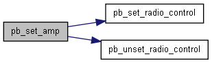
| SPINCORE_API int pb_set_amp | ( | float | amp, | |
| int | addr | |||
| ) |
Set the value of one of the amplitude registers.
- Parameters:
-
amp Amplitude value. 0.0-1.0 addr Address of register to write to
- Returns:
- A negative number is returned on failure, and spinerr is set to a description of the error. 0 is returned on success.
| SPINCORE_API int pb_fft | ( | int | n, | |
| int * | real_in, | |||
| int * | imag_in, | |||
| double * | real_out, | |||
| double * | imag_out, | |||
| double * | mag_fft | |||
| ) |
Calculates the Fourier transform of a given set of real and imaginary points
- Parameters:
-
n Number of points for FFT. real_in Array of real points for FFT calculation imag_in Array of imaginary points for FFT calculation real_out Real part of FFT output imag_out Imaginary part of FFT output mag_fft Magnitude of the FFT output
- Returns:
- Returns zero.
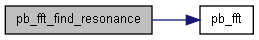
| SPINCORE_API double pb_fft_find_resonance | ( | int | num_points, | |
| double | SF, | |||
| double | SW, | |||
| int * | real, | |||
| int * | imag | |||
| ) |
Calculates the resonance frequency of a given set of real and imaginary points based on the maximum value of the magnitude of the Fourier transform.
- Parameters:
-
num_points Number of complex data points. SF Spectrometer Frequency used for the experiment (in Hz). SW Spectral Width used for data acquisition (in Hz). real Array of the real part of the complex data points. imag Array of the imaginary part of the complex data points.
- Returns:
- Returns the resonance frequency (in Hz).
| SPINCORE_API int pb_shift_data_left | ( | int | num_points, | |
| int | points_shift, | |||
| int | val_shift, | |||
| int * | real_in, | |||
| int * | imag_in, | |||
| int * | real_out, | |||
| int * | imag_out | |||
| ) |
Shifts the data left a specified number of points and replaces the right most points with a specified value
- Parameters:
-
num_points Number of complex data points. points_shift Number of points to shift to the left. val_shift Value to make the right most points. real_in Input array of the real part of the complex data points. imag_in Input array of the imaginary part of the complex data points. real_out Output array of the real part of the complex data points. imag_out Output array of the imaginary part of the complex data points.
- Returns:
- Returns the resonance frequency (in Hz).
| SPINCORE_API int pb_shift_data_right | ( | int | num_points, | |
| int | points_shift, | |||
| int | val_shift, | |||
| int * | real_in, | |||
| int * | imag_in, | |||
| int * | real_out, | |||
| int * | imag_out | |||
| ) |
Shifts the data right a specified number of points and replaces the left most points with a specified value
- Parameters:
-
num_points Number of complex data points. points_shift Number of points to shift to the right. val_shift Value to make the left most points. real_in Input array of the real part of the complex data points. imag_in Input array of the imaginary part of the complex data points. real_out Output array of the real part of the complex data points. imag_out Output array of the imaginary part of the complex data points.
- Returns:
- Returns the resonance frequency (in Hz).