Implementation of Analog Modulation on SpinCore
PulseBlasterDDS And RadioProcessor Boards
Introduction:
Analog modulation refers to
the process of transferring an analog baseband
(low frequency) signal, like an audio or TV
signal over a higher frequency signal such as a
radio frequency band.
There
are two ways to modulate an RF carrier:
1.
Amplitude Modulation
In analog
modulation, the amplitude of the carrier signal
is made to follow that of the modulating signal.
Several variants of amplitude modulation are
used in practice. They are Double Side Band
Suppressed Carrier (DSBSC) Modulation, Single
Sideband Suppressed Carrier (SSBSC) Modulation
and Vestigial Sideband Amplitude Modulation
(VSBAM).
PBDDS
Board Implementation:
For generation of AM
waveforms on SpinCore PulseBlasterDDS Boards,
the basic form of amplitude modulation is given
by:
AM (t) =
Ca*sin(wc*t)*[A+(Ma*sin(wm*t))]
For this formula:
t = time
Ca = amplitude of Carrier waveform (1 Vp-p here)
wc = angular frequency of the carrier signal in
radians/sec
wm = angular frequency of the modulating signal
in radians/sec
Ma = amplitude of the modulating waveform.
AM(t) = the resulting AM waveform
A and Ma are set and scaled so that the
amplitude of [A+(Ma*Sin(wmt))] does not exceed
the value of 1Vp-p for the given modulation
index.
The scaling factor and the values are chosen by
the formula given below:
Ma = 1/((100/MI) + 1)
Where MI=Modulation Index specified by the user
in between 0-100% value. And A = Ma*100/MI
Note: Tm=1/Fm can
not be less than (9 * clock time period) for
proper results where Fm is the frequency of the
message signal in Hz.
The carrier waveform
and the message signals can be generated using
the PulseBlasterDDS and RadioProcessor's NCO and
AWG respectively.
The generation of
carrier waveform in C code is as below :
void shape_make_carrier (float
*dds_data)
{
int i;
for (i = 0; i < 1024; i++)
{
dds_data[i] = sin (2.0 * pi * ((float) i /
1024.0));
}
}
The message signal
in which amplitude is scaled in accordance with
modulation index is generated as given below.
void shape_make_sin (float
*shape_data)
{
int i;
float MI, A, Ma;
printf ("Enter Modulation
Index from 0 to 100 percent: ");
scanf ("%f", &MI);
Ma = 1/((100/MI) + 1);
A = Ma*100/MI ;
for (i = 0; i < 1024;
i++)
{
shape_data[i] = A+(Ma*sin (2.0 * pi *
((float) i / 1024.0)));
}
}
Both the above
generated signals are loaded in the board by
using the SpinAPI function as given below:
pb_dds_load
(shape_data, DEVICE_SHAPE);
pb_dds_load (dds_data, DEVICE_DDS);
The
complete C code demonstrating this
implementation is available for direct
download. The code generates an amplitude
modulated wave for any given modulation index,
carrier frequency, and message signal frequency.
In the code, the message signal is assumed to be
a sine wave, but the user can edit the code to
make the message signal into any waveform.
Some examples of output obtained with this code
is given below. Note that the code only
demonstrates a basic version of amplitude
modulation. A similar setup can also be used for
the DSBSC, SSBSC and VSBAM techniques mentioned
above.
|
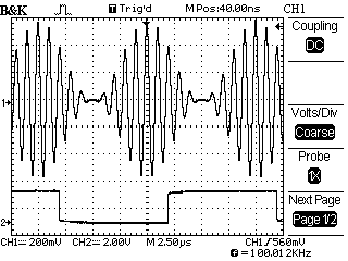
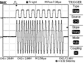
Figure 1
shows the output AM waveform generated.
Channel 1 shows the ouput AM wave for
carrier frequency Fc =1 MHz and a
message signal frequency of Fm = 100 kHz
and modulation index = 100%.
Channel 2 shows the TTL output with
frequency = Fm/2. Each cycle of the TTL
output corresponds to the time taken to
execute the two SpinAPI functions given
below:
pb_inst_radio_shape (0, 0, 0,
0, TX_ENABLE, NO_PHASE_RESET,
NO_TRIGGER,
USE_SHAPE, 0,
0x0F, CONTINUE, 0, (1/fm) * us);
pb_inst_radio_shape
(0, 0, 0, 0, TX_ENABLE,
NO_PHASE_RESET, NO_TRIGGER,
USE_SHAPE, 0,
0x00, BRANCH, start, (1/fm) * us);
The execution of these instructions
results in the generation of two full
cycles of the AM signal.
Also note
that Channel 1 is delayed by (9 * clock
cycle) time period.
|
|
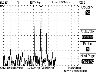
Figure 2 shows the frequency spectrum of
the output AM waveform for the
specifications given in Figure 1.
The carrier is centered around at 1 MHz
and two sidebands are present at 900 kHz
and 1100 kHz. The sidebands are offset
from the carrier by the frequency of the
modulating signal.
This basic variant of AM has a prominent
carrier signal displayed in the
frequency spectrum. Some of the other
methods of achieving AM mentioned, such
as DSBSC and SSBSC above are designed to
reduce this carrier component in the
frequency spectrum. Methods such as
SSBSC and VSBAM are designed to remove
or suppress one of the sidebands.
|
|
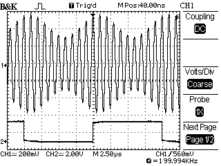
Figure 3
shows an AM waveform generated using the
example code.
Channel 1
shows the ouput AM wave for a carrier
frequency Fc = 1 MHz and message signal
frequency Fm = 100 kHz with Modulation
Index = 30%.
Channel 2
shows the TTL output with frequency =
Fm/2.
|
2.
Angle Modulation
In Angle Modulation, the message signal's
amplitude is used to control the frequency or
phase of the carrier signal. This gives rise to
the two methods known as Frequency Modulation
and Phase Modulation, respectively.
Frequency
Modulation implementation on SpinCore
PulseBasterDDS Boards:
In the SpinCore
PulseBasterDDS board, the frequency modulated
waveform is generated using the NCO by
controlling the frequency registers in
accordance with the instantaneous amplitude of
the message signal using the PulseBlaster Timing
Core.
The complete C code demonstrating this
implementation is available for direct
download.
The code performs basic frequency modulation
using a sinusoidal carrier for any given carrier
frequency within the board specifications. The
message signal is also assumed to be a sine
wave, as in the case of amplitude modulation.
This code can be extended to use different types
of carrier and message signals.
The equation implemented in the code is:
FM(t)= Ca*sin(wc*t + phi)
For this formula:
phi = change in the frequency of the carrier
with respect to amplitude of modulating
waveform.
wc = angular frequency of the carrier signal in
radians/sec (also equal to 2*pi*fc)
Ca = amplitude of the carrier signal (set to 1
in the code)
FM(t) = the resulting FM waveform
The modulating signal chosen is a sine wave as
given by:
m(t) = Ma*sin(wm*t)
For this formula:
m(t) = the modulating or message signal
wm = angular frequency of the message signal in
radians/sec (also equal to 2*pi*fm)
Ma = amplitude of the modulating signal (set to
1 in the code)
Also, in this example, the TTL outputs are used
to trigger the oscilloscope.
Following the similar method described in
amplitude modulation, the carrier and message
signal is generated in the C code.
In this implementation, the modulating waveform
amplitude (which is in the range of -1V to +1V)
is quantized into a number of value as set by
the user (with greater numbers offering a better
FM implementation). These values are in turn
used to compute one of that many possible
frequency shifts around the carrier frequency.
This is done by choosing a step size such that a
+1V amplitude would produce a shift resulting in
a instantaneous carrier frequency of fs + (fm/2)
and a -1V would result in fs - (fm/2). The
quantization size should be set to the number of
frequency registers available on the particular
SpinCore PulseBlasterDDS or RadioProcessor board
being used. If more frequency registers are
desired, please contact SpinCore.
The frequency registers can be loaded with the
required value by using the following SpinAPI
functions.:
for
(i=0;i<N;i++)
{
pb_set_freq (fc[i]);
}
where fc[i] contains the values of the frequency
shift in accordance to the quantized amplitude.
The SpinAPI functions used for frequency
modulation is given by:
pb_inst_radio(i,0,0,0,
TX_ENABLE, NO_PHASE_RESET, NO_TRIGGER,
0xFF,CONTINUE, 0, Ti*ns);
where the index "i" represents the ith frequency
register.
Some examples of output obtained with this code
is given below. Note that the code only
demonstrates a basic version of frequency
modulation. It can also be used to implement the
phase modulation by using the phase registers of
the PulseBlasterDDS and RadioProcessor boards
instead of the frequency registers.
Figure 4:
In this example, for the purpose of
visualizing the results on the
oscilloscope, the instantaneous
frequency of the carrier signal is
quantized to only 9 possible values.
The figure shows the output FM waveform
on channel 2 with TTL outputs on Channel
1 being used for triggering the
oscilloscope for a carrier frequency of
Fc = 1 MHz and a message signal
frequency of Fm = 500 kHz.
Each pulse in the TTL waveform
corresponds to the execution of an
instruction that generates a portion of
the FM signal corresponding to 1/9th of
the period of the message signal.
|
Figure 5
is the result obtained with the same
parameters that were used in the
previous example. Here, the number of
frequency values for the carrier signal
was quantized to 5 values to give a even
better visualization of the frequency
modulation.
|
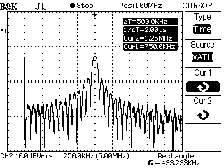
Figure 6
shows the FM spectrum on channel 2
of the oscilloscope when 1024 frequency
values are used in the carrier signal.
The same parameters as the examples
given above were used for this example
as well.
|
|