|
PulseBlasterDDS-III-100: Programmable TTL and
Direct Digital Synthesis RF Pulse Generator
| Specifications |
|
Applications |
|
Ordering Information |
|
Manuals, etc. |
|
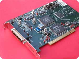
PulseBlasterDDSTM is a
general-purpose, intelligent, programmable, RF and TTL/CMOS
pulse/pattern generator system (PCI or ISA board or a portable
stand-alone system). The PulseBlasterDDSTM
series of Intelligent Pulse Generation boards from SpinCore
Technologies, Inc., couples SpinCore’s unique Intelligent Pulse Timing
Processor core, dubbed PulseBlasterTM, with Direct Digital
Synthesis (DDS) technology for use in system control and
radio-frequency (RF) pulse generation. The PulseBlasterTM
processor, implemented in state-of-the-art programmable logic, provides
all the necessary timing control signals required for overall system
control and pulse synchronization. By adding DDS features,
PulseBlasterDDSTM can now meet all the excitation/stimuli
needs of demanding users. PulseBlasterDDSTM provides users
the ability to control their systems through the generation of both
digital control signals and fully synchronized excitation RF pulses
from a small form factor PC board, providing users a compelling
price/performance proposition unmatched by any other device on the
market today.
Architecture
This
figure presents the general architecture of the PulseBlasterDDS-III-100
system. The two major building blocks are the DDS Core and the
Pulse Programming and Timing Processor Core (PP Core). The DDS Core
contains a Numerically Controlled Oscillator (NCO) and has 16
programmable frequency registers that are under the pulse program
control. Prior to gating, the DDS signal can be phase offset by
one of 16 programmable phase registers for two independent output
channels. The PP Core controls the timing of the gating pulses
and provides the necessary control signals for frequency and phase
registers. The DDS and PP cores have been integrated onto a
single silicon chip. High performance DAC chips and high current
output amplifiers complement the design.
Benefits of DDS Technology
- Generation of any frequency from DC to 1/2 reference
clock oscillator in milliHertz tuning steps (32 bit digital
resolution)!
- Agile relative phase control using up to 16
programmable phase registers per channel, 12-bit phase
resolution. Pipeline delay of only 3 reference clock
cycles.
- Agile, phase coherent, "zero-time" frequency
switching using 16 independent frequency registers.
- Agile pulsed RF output, 10 ns resolution (100 MHz
models).
- Easy tuning of frequency outputs.
- Greater immunity to parameter drift due to
temperature.
What does SpinCore's Intelligent Pattern
Generation give users?
- Timing resolution of 10 ns at a 100 MHz master clock
(NOTE: Timing resolution of 2.5 ns is available on non-DDS, TTL-only
PulseBlasterESR boards operating up to 400 MHz).
- 10 to 24 independent output bits.
- Simple instruction set.
- Memory space for up to 32k program words (VLIW,
80-bit wide).
- External hardware and software triggering.
- 3.3 V or 5 V (ISA boards only) digital TTL/CMOS
outputs, 25 mA per pin. Output bits can be combined to increase
the max. load current.
- Multi-board synchronization.
Added benefits
- Small size and low power consumption.
- Low level and high level programming support.
- Free technical support; extended support available.
Output Signals
This exciting product comes with up to three analog
output channels and 10 TTL/CMOS channels, all independently controlled
and synchronized. The analog channels can output RF/IF
frequencies down to programmable DC levels. By providing multiple
options, PulseBlasterDDSTM can be your complete excitation
device for NMR, NQR, MRI, or related resonance and test
technologies. If more output channels are required, multiple
boards can be synchronized to provide as many digital output bits or
RF/IF channels as necessary. The frequency and phase of the RF
pulses generated by the DDS output channels are under the complete
control of the user and are specified through software programming.
PulseBlasterDDSTM also provides the ability to gate the
output of the DDS channels allowing for independent pulsed RF operation
of the output channels. Digital sampling rates of the output waveforms
up to 100 MHz are supported.
External Triggering and Cascading
PulseBlasterDDSTM can be triggered and/or
reset externally via dedicated hardware lines. The two separate
lines combine the convenience of triggering (e.g., in cardiac gating)
with the safety of the "stop/reset-to-zero" line. The required
control signals are active low (or short to ground). The design
also allows for multiple boards to be synchronized, easily extending
the available output pattern to more bits and/or more RF/IF
channels. The "Wait-for-event" feature is standard.
Sample NMR Application: Complete RF
Larmor digital excitation system
Just add a power amplifier to have a complete RF Larmor
digital excitation system for low-field NMR, MRI, and NQR systems (see
Application Note). Use for 129Xe NMR, retrofit your
older console, revive your old electromagnet, try NMR with
permanent magnets, etc.
Other
related applications:
- Complete high IF digital excitation system for high
field NMR/MRI (just add mixers!).
- Complete bench test equipment for solid-state NMR
probes (just add mixer and power amplifier!) - eliminates the need for
wasting the precious magnet time.
- Build a multi-qubit NMR quantum computing device at a
fraction of the cost of other solutions.
- Use it for all-digital CRAMPS, SFAM, and other
"exotic" solid-state NMR experiments.
- Build a lock system.
- Build a demostration NMR system with/for your
students
- Use it for Senior-Project and Masters' classes.
- Use with your microcoil probe.
- Build and control your own equipment for "hyphenated"
experiments, LC-NMR, etc.
- For more ideas, please vistit our Applications page
Ordering Information
- Choose between one, two, or three RF output channels
(Models -I or -II, or -III);
- Choose between 50 or 100 MHz Reference Clock
Frequency (Models -50 or -100);
- Choose between ISA or PCI board (Models -PCI or -ISA)
Sample Part Number:
PBDDS-III-100-PCI.
| Model |
Number of RF Output
Channels |
Clock Frequency |
Memory Words |
Form-factor |
| PBDDS-III-100-32k |
3 |
100 MHz |
32k |
PCI |
To inquire about the availiability and pricing of our PulseBlasterDDS line of products,
please use our Contact Form.
Models
- Configuration DDS-III
- Three DDS RF/IF outputs and 10 TTL/CMOS outputs. In this
configuration, one RF output can drive the transmitter. The
remaining two other RF outputs provide two orthogonal signals for two
phase-sensitive quadrature detectors. To accomodate for
propagation delays, the orthogonality of the Rx channels can be
adjusted with 12-bit precision, i..e, in 4096 steps (0.09
degree). The Tx and Rx channels are independently gated.
Agile frequency and phase switching with a zero-time latency, phase
coherent, ideal for chirp pulses, etc. Up to 100 MHz reference
clock oscillator. TTL/CMOS lines are synchronized with RF
pulses. RF and TTL/CMOS pulses from 90 ns to over two years in
duration, 10 ns timing resolution. Program space - up to 32k
words, including loops (nested up to 8 levels deep), subroutines, and
the "Wait-for-event" funtion with user-programmable response time.
- Configuration DDS-II
- Two DDS RF outputs and 10 TTL/CMOS outputs. The two DDS
outputs are independenly gated and phase-offset, e.g., for quadrature
DDS signal generation. The 10 TTL/CMOS outputs are all
independently controlled and can deliver 25 mA per channel; channels
can be combined together to provide more output current. This is
the most popular configuration - it can be used to provide independent
Tx (excitation) and Rx (reference) signals for NMR, NQR, etc., where
the Rx phase-coherent signal is used for signal detection.
Agile frequency and phase switching with a zero-time latency, phase
coherent, ideal for chirp pulses, etc. Up to 100 MHz reference
clock oscillator. TTL/CMOS lines are synchronized with RF
pulses. RF and TTL/CMOS pulses from 90 ns to over two years in
duration, 10 ns timing resolution. Program space - up to 32k
words, including loops (nested up to 8 levels deep), subroutines, and
the "Wait-for-event" funtion with user-programmable response time.
- Configuration DDS-I
- Single DDS RF output and 10 TTL/CMOS outputs. Ideal for
applications where one RF generator channel is required. Up to 100 MHz
reference clock oscillator. This configuration can be provided
with a special, clock-doubling DAC chip. TTL/CMOS lines are
synchronized with RF pulses. RF and TTL/CMOS pulses from 90 ns to
over two years in duration, 10 ns timing resolution. Agile
frequency and phase switching with a zero-time latency, phase coherent,
ideal for chirp pulses, etc. Program space - up to 32k words,
including loops (nested up to 8 levels deep), subroutines, and the
"Wait-for-event" funtion with user-programmable response time.
Customer Designs
- Spin-Decoupler. Autonomous, pre-programmed RF
generator customized for NMR/MRI decoupling applications. To
simplify the pulse-sequence programming, WALTZ and MLEV decoupling
sequences are hard-coded via firmware and can be selected with an
external TTL signal. The RF output frequency and pulse lengths
can be controlled via a simple ASCII RS232 serial interface. The
RF output power is approx. 10 dBm.
- Clock Generator. Single square-wave
output of DDS-derived frequencies, 32 bits of frequency precision
(47 mHz at 100 MHz reference oscillator frequency), may be used for
driving digital systems as a digital clock generator; simplified
programming interface.
- Additional DDS channels - each channel may have
independently controlled frequency and phase, and all channels can be
independently gated. The channels could be used to drive independent
transmitters, e.g., for multidimensional and/or multi-qubit NMR quantum
computing. Compare and save - the excitation part of an 8-qubit
NMR quantum computer could be built with just two PulseBlasterDDSTM
boards!
- Stand-alone system USB (or RS-232) controlled.
- GPS-locked reference clock oscillator.
Product Manual
Programming
To complement the power and performance of the
PulseBlasterDDSTM board, the software programming of the
board is straightforward. The programming architecture,
based on the Very-Long-Instruction-Word (VLIW) concept, assures that
all RF and DAC events are always properly synchronized with the timing
control signals generated by PulseBlasterTM pulse programmer
core. The 32k memory depth and powerful flow control
statements allow the most complicated patterns/sequences to be executed
with ease. The PulseBlasterDDSTM board can run
under Microsoft Windows operating systems, including XP. The
control
software can be compiled to operate under other operating systems as
well.
Free Software Support
- Available as a part of the SpinAPI Package:
- Example programs (executables and C source files)
- PulseBlaster Interpreter for easy programming without writing C code
- The SpinAPI package available for download on the Software Downloads page.
- Interfaces and examples - LabView, Matlab, IGOR-PRO, Visual Basic, Custom GUI.
Warranty Information
- Standard warranty - two years
- Longer warranty periods available
- Money-back guarantee – 30 days.
|

